

- On screen Keyboard – osk
- Calculator – calc
- WordPad – write
- Windows Media Player – wmplayer
- Windows Fax and Scan – wfs
- Snipping Tools – snippingtool
- Paint – mspaint
- Notepad – notepad
- Task manager – taskmgr
- Sticky Notes – stikynot
- Math Input Panel – mip
- Command Prompt – cmd
- Powershell – powershell
- Windows Journal – journal
- Narrator – narrator
- Magnifier – magnify
- Edge – microsoft-edge://
- Internet Explorer – iexplore
- Bluetooth – fsquirt
- Windows Firewall – firewall.cpl
- Windows Firewall with Advanced Security – wf.msc
- Windows Explorer – explorer
- XPS Viewer – xpsrchvw
- System Configuration – msconfig
- System Configuration Editor – sysedit
- System Information – msinfo32
- System Properties – sysdm.cpl
- System Properties (Advanced Tab) – systempropertiesadvanced
- System Properties (Computer Name Tab) – systempropertiescomputername
- System Properties (Hardware Tab) – systempropertieshardware
- System Properties (Remote Tab) – systempropertiesremote
- System Properties (System Protection Tab) – systempropertiesprotection
- Open Documents Folder – documents
- Open Videos folder – videos
- Open Downloads Folder – downloads
- Open Favorites Folder – favorites
- Open Recent Folder – recent
- Control Panel – control
- Personalization & Themes – control desktop
- Personalization & Color – control color
- File explorer properties & Folder Options – control folders
- Keyboard Properties – control keyboard
- Mouse Properties – control mouse
- Network Properties – control netconnections
- Printers Properties – control printers
- Manage current user Account – control userpasswords
- Manager all User Accounts – control userpasswords2
- Create Repair Disc – recdisc
- Backup and Restore – sdclt
- Remote Assistance – msra
- To Open Recently Viewed files – recent
- To Connect to a Projector – displayswitch
- To add a New Device – devicepairingwizard
- Open Ease of Access centre – utilman
- User Account Control Settings – useraccountcontrolsettings
- Windows Task scheduler – taskschd.msc
- System Restore – rstrui
- All System information – msinfo32
- Network Connections – ncpa.cpl
- System Configuration – msconfig
- Disk Cleanup – cleanmgr
- Disk Defragmenter – dfrgui
- Disk Management – diskmgmt.msc
- Malicious Software Removal Tool – mrt
- Problem Steps Recorder – psr
- Internet Options – inetcpl.cpl
- Device Manager – devmgmt.msc
- Computer Management – compmgmt.msc
- Shared Folders – fsmgmt.msc
- Create a shared folder wizard – shrpubw
- Backup and restore user name and passwords – credwiz
- Region and Language – intl.cpl
- Registry Editor – regedit
- Local Group Policy Editor – gpedit.msc
- Indexing Options – rundll32.exe shell32.dll,Control_RunDLL srchadmin.dll
- Resource Monitor – resmon
- Sound settings – mmsys.cpl
- Troubleshooting – control.exe /name Microsoft.Troubleshooting
- User Accounts – control.exe /name Microsoft.UserAccounts
- Local Users and Groups – lusrmgr.msc
- Advanced User Accounts – netplwiz
- Time and Date – timedate.cpl
- Screen Resolution – desk.cpl
- Color Management – colorcpl
- Event Viewer – eventvwr.msc
- Remote Desktop Connection – mstsc
- Services – services.msc
- Certificates – certmgr.msc
- Mouse settings – main.cpl
- Know current Windows version – winver
- Local Security Policy – secpol.msc
- Directly go to list of installed programs – appwiz.cpl
- Windows Update settings – control update
- Administrative Tools – control admintools
- Scheduled Tasks – control schedtasksOpen Pictures Folder – pictures
- System Restore – rstrui
- Display Color Calibration – dccw
- Display – dpiscaling
- Display Switch – displayswitch
- Driver Verifier Manager – verifier
- File Signature Verification – sigverif
- Game Controllers – joy.cpl
- Getting Started – gettingstarted
- iSCSI Initiator Configuration Tool – iscsicpl
- Language Pack Installer – lpksetup
- Microsoft Management Console – mmc
- Microsoft Support Diagnostic Tool – msdt
- Performance Monitor – perfmon.msc
- Phone and Modem telephon – cpl
- Phone Dialer – dialer
- WMI Management – wmimgmt.msc
- Windows Disc Image Burning Tool – isoburn
- Windows DVD Maker – dvdmaker
Author: smartitsoluction
I am Sharing about My Experience ....
CREATING AND CONFIGURING VLANS
First step on any Layer 3 switch is to create the necessary VLANs.
By default, VLAN1 exists on every switch. VLAN1 is also known as the Management VLAN and it's highly advisable
VLAN1 is not used to carry user data/traffic, as VLAN1 is used only for the management of the network’s switches.
Company traffic (Servers, workstations etc) should be placed on a different VLAN, for example, VLAN2. Voice traffic
e.g IP Phones, CallManager, CallManager Express or Voice Gateways, should also be placed on a VLAN of their
own – also known as the Voice VLAN.
As part of the design and implementation phase, we strongly advise to create a list of the VLANs that will be created
along with their name and any additional information to help identify their purpose and of course the IP address that
will be assigned to every VLAN interface on the core Layer 3 switch. This will ensure all VLANs are created and
everything is documented for future reference.
Below is an example of a VLAN list we created during the installation of our Cisco Catalyst 3560G:
Before we begin creating our VLANs, let’s take a look and see the default VLANs that exist on Catalyst Layer 3
switches using the show vlan briefcommand:
C3560G# show vlan brief
VLAN Name Status Ports
—- ——————————– ——— ——————————-
1 default active Gi0/1, Gi0/2, Gi0/3, Gi0/4
Gi0/5, Gi0/6, Gi0/7, Gi0/8
Gi0/9, Gi0/10, Gi0/11, Gi0/12
Gi0/13, Gi0/14, Gi0/15, Gi0/16
Gi0/17, Gi0/18, Gi0/19, Gi0/20
Gi0/21, Gi0/22, Gi0/23, Gi0/24
Gi0/25, Gi0/26, Gi0/27, Gi0/28
Gi0/29, Gi0/30, Gi0/31, Gi0/32
Gi0/33, Gi0/34, Gi0/35, Gi0/36
Gi0/37, Gi0/38, Gi0/39, Gi0/40
Gi0/41, Gi0/42, Gi0/43, Gi0/44
Gi0/45, Gi0/46, Gi0/47, Gi0/48
Gi0/49, Gi0/50, Gi0/51, Gi0/52
1002 fddi-default act/unsup
1003 token-ring-default act/unsup
1004 fddinet-default act/unsup
1005 trnet-default act/unsup
First step is to create and name the new VLANs in the switch’s VLAN database. This is accomplished by using
the vlan command, followed by the name command. Depending on the switch model, these commands might or
might-not appear in the configuration:
C3560G(config)# vlan 2
C3560G(config-vlan)# name Data-VLAN
C3560G(config-vlan)# vlan 3
C3560G(config-vlan)# name Voice-VLAN
C3560G(config-vlan)# vlan 4
C3560G(config-vlan)# name IP-Cameras
C3560G(config-vlan)# vlan 5
C3560G(config-vlan)# name Mgnt-WiFi
C3560G(config-vlan)# vlan 6
C3560G(config-vlan)# name Company-WiFi
C3560G(config-vlan)# vlan 7
C3560G(config-vlan)# name PDA-WiFi-VLAN
C3560G(config-vlan)# vlan 8
C3560G(config-vlan)# name Guest-VLAN
C3560G(config-vlan)# end
We can verify the new VLANs have been created in the VLAN database by issuing the show vlan brief command:
C3560G# show vlan brief
VLAN Name Status Ports
—- ——————————– ——— ——————————-
1 default active Gi0/1, Gi0/2, Gi0/3, Gi0/4
Gi0/5, Gi0/6, Gi0/7, Gi0/8
Gi0/9, Gi0/10, Gi0/11, Gi0/12
Gi0/13, Gi0/14, Gi0/15, Gi0/16
Gi0/17, Gi0/18, Gi0/19, Gi0/20
Gi0/21, Gi0/22, Gi0/23, Gi0/24
Gi0/25, Gi0/26, Gi0/27, Gi0/28
Gi0/29, Gi0/30, Gi0/31, Gi0/32
Gi0/33, Gi0/34, Gi0/35, Gi0/36
Gi0/37, Gi0/38, Gi0/39, Gi0/40
Gi0/41, Gi0/42, Gi0/43, Gi0/44
Gi0/45, Gi0/46, Gi0/47, Gi0/48
Gi0/49, Gi0/50, Gi0/51, Gi0/52
2 Data-VLAN active
3 Voice-VLAN active
4 IP-Cameras active
5 Mgnt-WiFi active
6 Company-WiFi active
7 PDA-WiFi-VLAN active
8 Guest-VLAN active
VLAN Name Status Ports
—- ——————————– ——— ——————————-
1002 fddi-default act/unsup
1003 token-ring-default act/unsup
1004 fddinet-default act/unsup
1005 trnet-default act/unsup
The show vlan brief command is very useful as it not only shows the vlans created, but the switch ports assigned to
each VLAN. We can quickly identify which ports might be assigned to a specific VLAN. Since this is a new switch, all
ports are assigned to VLAN1, the Management VLAN, but this is about to change.
Note that created VLANs are stored in the switch’s VLAN database. The VLAN database is a file named vlan.dat and
is located in the switch’s FLASH memory:
C3560G# dir flash:
Directory of flash:/
2 -rwx 976 Mar 1 1993 00:04:52 +00:00 vlan.dat
3 -rwx 2110 Mar 1 1993 00:03:54 +00:00 config.text
4 -rwx 5 Mar 1 1993 00:03:54 +00:00 private-config.text
7 drwx 192 Mar 1 1993 00:09:28 +00:00 c3560-ipbase-mz.122-35.SE5
32514048 bytes total (23457280 bytes free)
Looking carefuly at the creation/modified date of the files, it seems like we are off by a bit more than 10 years, so it is
evident the correct date and time have not yet been configured. We’ll take care of this later.
Next, we create our VLAN interfaces and assign IP addresses and descriptions:
interface Vlan1
description Core-Network
ip address 172.16.10.1 255.255.255.0
!
interface Vlan2
description Data-VLAN
ip address 192.168.0.1 255.255.255.0
!
interface Vlan3
description Voice-VLAN
ip address 192.168.3.1 255.255.255.0
!
interface Vlan4
description IP-Cameras-VLAN
ip address 192.168.4.1 255.255.255.0
!
interface Vlan5
description Mgnt-WiFi-VLAN
ip address 192.168.5.1 255.255.255.0
!
interface Vlan6
description Company-WiFi-VLAN
ip address 192.168.6.1 255.255.255.0
!
interface Vlan7
description PDA-WiFi-VLAN
ip address 192.168.7.1 255.255.255.0
!
interface Vlan8
description Guest-VLAN
ip address 192.168.8.1 255.255.255.0
!
Note: When configuring the new VLAN interfaces, the switch will show the following message on the console for each
VLAN interface configured: %LINEPROTO-5-UPDOWN: Line protocol on Interface Vlan2, changed state to
down. This message can safely be ignored as the VLAN Line protocol will come up as soon as ports on the switch
are assigned to the VLAN.
There is a possibility that Interface VLAN1 might have the shutdown command configured. This can be checked by
issuing the show runcommand. In the case the shutdown command is present under VLAN1 interface, it is
imperative to issue the no shutdown command so that the Management VLAN interface comes up.
The show ip interface brief command will verify all VLANs are up (Status), but with a protocol down status as
explained earlier:
C3560G# show ip interface brief
Interface IP-Address OK? Method Status Protocol
Vlan1 172.16.10.1 YES manual up down
Vlan2 192.168.0.1 YES manual up down
Vlan3 192.168.3.1 YES manual up down
Vlan4 192.168.4.1 YES manual up down
Vlan5 192.168.5.1 YES manual up down
Vlan6 192.168.6.1 YES manual up down
Vlan7 192.168.7.1 YES manual up down
Vlan8 192.168.8.1 YES manual up down
ENABLE SVI INTERVLAN ROUTING – IP ROUTING & CONFIGURING DEFAULT GATEWAY
A Switch Virtual Interface (SVI) is a VLAN of switch ports represented by one interface to a routing or bridging
system. Since there is no physical interface for the VLAN, the SVI provides the Layer 3 processing for packets from
all switch ports associated with the VLAN. Once VLANs have been created and VLAN interfaces are configured with
their IP addresses, we can enable ip routing on our switch, effectively switching ‘on’ the InterVLAN routing capabilities
of the switch and enabling the supported routing protocols.
Let’s take a look at the routing capabilities before enabling ip routing. This can be done using the show ip
route command:
C3560G# show ip route
Default gateway is not set
Host Gateway Last Use Total Uses Interface
ICMP redirect cache is empty
Windows 10 Command
Windows 10 Command Prompt keyboard co
| Function | Command |
| SHIFT + LEFT ARROW | Moves the cursor to the left one character, extending the selection |
| SHIFT + RIGHT ARROW | Moves the cursor to the right one character, extending the selection |
| SHIFT + UP ARROW | Selects text up line by line starting from the location of the insertion point |
| SHIFT + DOWN ARROW | Extends text selection down one line, starting at the location of the insertion point |
| SHIFT + END | If cursor is in current line being edited* First time extends selection to the last character in the input line.* Second consecutive press extends selection to the right margin; or else Selects text from the insertion point to the right margin. |
| SHIFT + HOME | If cursor is in current line being edited* First time extends selection to the character immediately after the command prompt.* Second consecutive press extends selection to the left margin; or else Extends selection to the left margin. |
| SHIFT + PAGE DOWN | Extends selection down one screen |
| SHIFT + PAGE UP | Extends selection up one screen |
| CTRL + SHIFT + RIGHT ARROW | Extends the selection one word to the right |
| CTRL + SHIFT + LEFT ARROW | Extends the selection one word to the left |
| CTRL + SHIFT + HOME | Extend selection to the beginning of the screen buffer |
| CTRL + SHIFT + END | Extend selection to the end of the screen buffer |
| CTRL + A | If cursor is in current line being edited (from first typed char to last type char) and line is not empty, and any selection cursor is also within the line being edited Selects all text after the prompt (phase 1); or else Selects the entire buffer (phase 2) |
| CTRL + V | Paste text into the command line |
| SHIFT + INS | Paste text into the command line |
| CTRL + C | Copy selected text to the clipboard |
| CTRL + INS | Copy selected text to the clipboard |
| CTRL + M | Enter “Mark Mode” to move cursor within window |
| ALT | In conjunction with one of the selection key combinations, begins selection in block mode |
| ARROW KEYS | Move cursor in the direction specified |
| PAGE KEYS | Move cursor by one page in the direction specified |
| CTRL + HOME | Move cursor to beginning of buffer |
| CTRL + END | Move cursor to end of buffer |
| CTRL + UP ARROW | Moves up one line in the output history |
| CTRL + DOWN ARROW | Moves down one line in the output history |
| CTRL + PAGE UP | Moves up one page in the output history |
| CTRL + PAGE DOWN | Moves down one page in the output history |
| CTRL + F | Opens “Find” in console dialog |
| ALT + F4 | Close the console window, of course! |
Installing and Configuring FTP 7 on IIS 7
Installing FTP for IIS 7.5
IIS 7.5 for Windows Server 2008 R2
-
- On the taskbar, click Start, point to Administrative Tools, and then click Server Manager.
- In the Server Manager hierarchy pane, expand Roles, and then click Web Server (IIS).
- In the Web Server (IIS) pane, scroll to the Role Services section, and then click Add Role Services.
- On the Select Role Services page of the Add Role Services Wizard, expand FTP Server.
- Select FTP Service. > [!NOTE] > To support ASP.NET Membership or IIS Manager authentication for the FTP service, you will also need to select FTP Extensibility.
- Click Next.
- On the Confirm Installation Selections page, click Install.
- On the Results page, click Close.
IIS 7.5 for Windows 7
- On the taskbar, click Start, and then click Control Panel.
- In Control Panel, click Programs and Features, and then click Turn Windows Features on or off.
- Expand Internet Information Services, then FTP Server.
- Select FTP Service. > [!NOTE] > To support ASP.NET Membership or IIS Manager authentication for the FTP service, you will also need to select FTP Extensibility.
- Click OK.
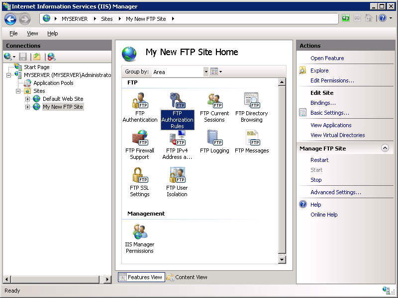
Creating a New FTP Site Using IIS Manager
The new FTP service makes it easy to create new FTP sites by providing you with a wizard that walks you through all of the required steps to create a new FTP site from scratch.
Step 1: Use the FTP Site Wizard to Create an FTP Site
In this first step you will create a new FTP site that anonymous users can open.
- pane.
- Create a folder at
%SystemDrive%\inetpub\ftproot - Set the permissions to allow anonymous access:
- Open a command prompt.
- Type the following command:
consoleCopy
ICACLS "%SystemDrive%\inetpub\ftproot" /Grant IUSR:R /T - Close the command prompt.

- Create a folder at
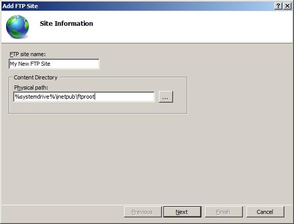
- When the Add FTP Site wizard appears:
- Enter “My New FTP Site” in the FTP site name box, then navigate to the
%SystemDrive%\inetpub\ftprootfolder that you created in the Prerequisites section. Note that if you choose to type in the path to your content folder, you can use environment variables in your paths. - When you have completed these items, click Next.

- Enter “My New FTP Site” in the FTP site name box, then navigate to the
- On the next page of the wizard:
- Choose an IP address for your FTP site from the IP Address drop-down, or choose to accept the default selection of “All Unassigned.” Because you will be using the administrator account later in this walk-through, you must ensure that you restrict access to the server and enter the local loopback IP address for your computer by typing “127.0.0.1” in the IP Address box. > [!NOTE] > If you are using IPv6, you should also add the IPv6 localhost binding of “::1”.
- Enter the TCP/IP port for the FTP site in the Port box. For this walk-through, choose to accept the default port of 21.
- For this walk- through, do not use a host name, so make sure that the Virtual Host box is blank.
- Make sure that the Certificates drop-down is set to “Not Selected” and that the Allow SSL option is selected.
- When you have completed these items, click Next.

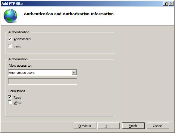
- On the next page of the wizard:
- Select Anonymous for the Authentication settings.
- For the Authorizationsettings, choose “Anonymous users” from the Allow access to drop-down, and select Read for the Permissions option.
- When you have completed these items, click Finish.


Summary
You have successfully created a new FTP site using the new FTP service. To recap the items that you completed in this step:
- You created a new FTP site named “My New FTP Site”, with the site’s content root at
%SystemDrive%\inetpub\ftproot. - You bound the FTP site to the local loopback address for your computer on port 21, and you chose not to use Secure Sockets Layer (SSL) for the FTP site.
- You created a default rule for the FTP site to allow anonymous users “Read” access to the files.
Step 2: Adding Additional FTP Security Settings
Creating a new FTP site that anonymous users can browse is useful for public download sites, but web authoring is equally important. In this step, you add additional authentication and authorization settings for the administrator account. To do so, follow these steps:
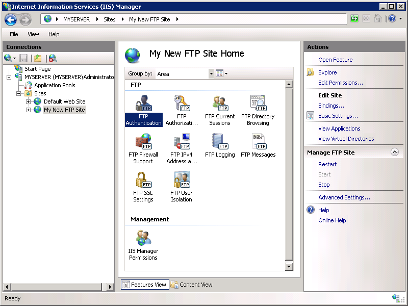
- In IIS Manager, click the node for the FTP site that you created earlier, then double-click FTP Authentication to open the FTP authentication feature page.

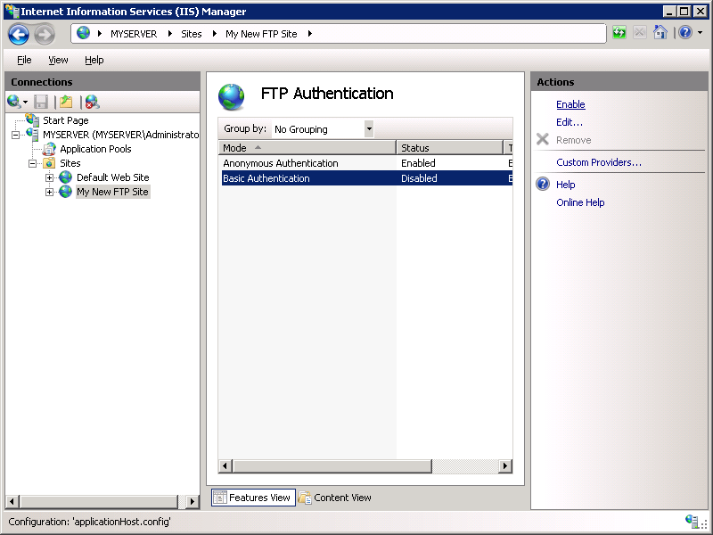
- When the FTP Authentication page displays, highlight Basic Authentication and then click Enable in the Actions pane.

- In IIS Manager, click the node for the FTP site to re-display the icons for all of the FTP features.
- You must add an authorization rule so that the administrator can log in. To do so, double-click the FTP Authorization Rules icon to open the FTP authorization rules feature page.

- When the FTP Authorization Rulespage is displayed, click Add Allow Rule in the Actions pane.

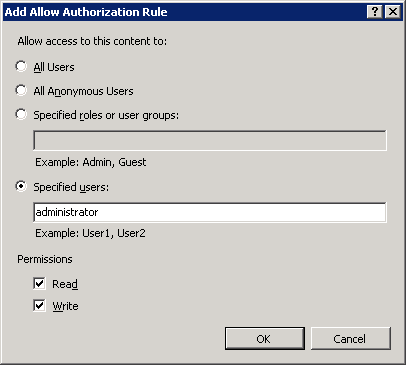
- When the Add Allow Authorization Rule dialog box displays:
- Select Specified users, then type “administrator” in the box.
- For Permissions, select both Read and Write.
- When you have completed these items, click OK.


Summary
To recap the items that you completed in this step:
- You added Basic authentication to the FTP site.
- You added an authorization rule that allows the administrator account both “Read” and “Write” permissions for the FTP site.
Step 3: Logging in to Your FTP Site
In Step 1, you created an FTP site that anonymous users can access, and in Step 2 you added additional security settings that allow an administrator to log in. In this step, you log in anonymously using your administrator account.
Cisco basic configuration commands .
| Command | descriptions |
| switch>? | The ? works here the same as in a router Used to get the list of all available commands |
| switch>enable | User mode, same as a router |
| switch# | Privileged mode |
| switch#disable | Leaves privileged mode |
| switch>exit | Leaves user mode |
| switch#show version | Displays information about software and hardware. |
| switch#show flash: | Displays information about flash memory (will work only for the 2900/2950 series). |
| switch#show mac-address-table | Displays the current MAC address forwarding table. |
| switch#show running-config | Displays the current configuration in DRAM. |
| switch#show startup-config | Displays the current configuration in NVRAM. |
| switch#show vlan | Displays the current VLAN configuration. |
| switch#show interfaces | Displays the interface configuration and status of line: up/up, up/down, admin down. |
| switch#show interface vlan1 | Displays setting of virtual interface VLAN 1, the default VLAN on the switch. |
To Reset Switch Configuration |
|
| Switch#delete flash:vlan.dat | Removes the VLAN database from flash memory. |
| Delete filename [vlan.dat]? | Press Enter |
| Delete flash:vlan.dat? [confirm] | Press Enter |
| Switch#erase startup-config | Erases the file from NVRAM. |
| Switch#reload | Restarts the switch. |
To Set Host Names |
|
| Switch#configure terminal | Moves to global configuration mode |
| Switch(config)#hostname Switch1 | Creates a locally significant host name of the switch. This is the same command as the router. |
| Switch1(config)# | |
| To Set Passwords | |
| Switch(config)#enable password vinita | Sets the enable password to vinita |
| Switch(config)#enable secret nikki | Sets the encrypted secret password to nikki |
| Switch(config)#line console 0 | Enters line console mode |
| Switch(config-line)#login | Enables password checking |
| Switch(config-line)#password vinita | Sets the password to vinita |
| Switch(config-line)#exit | Exits line console mode |
| Switch(config-line)#line vty 0 4 | Enters line vty mode for all five virtual ports |
| Switch(config-line)#login | Enables password checking |
| Switch(config-line)#password vinita | Sets the password to vinita |
| Switch(config-line)#exit | Exits line vty mode |
| Switch(config)# | |
To Set IP Addresses and Default Gateways |
|
| Switch(config)#interface vlan1 | Enters the virtual interface for VLAN 1, the default VLAN on the switch |
| Switch(config-if)#ip address 192.168.0.10 255.255.255.0 | Sets the IP address and netmask to allow for remote access to the switch |
| Switch(config-if)#exit | |
| Switch(config)#ip default-gateway 192.168.0.5 | Allows IP information an exit past the local network |
To Set Interface Descriptions |
|
| Switch(config)#interface fastethernet 0/1 | Enters interface configuration mode |
| Switch(config-if)#description Finance VLAN | Adds a description of the interface |
To Set Duplex Operation |
|
| Switch(config)#interface fastethernet 0/1 | Moves to interface configuration mode |
| Switch(config-if)#duplex full | Forces full-duplex operation |
| Switch(config-if)#duplex auto | Enables auto-duplex config |
| Switch(config-if)#duplex half | Forces half-duplex operation |
To Set Operation Speed |
|
| Switch(config)#interface fastethernet 0/1 | |
| Switch(config-if)#speed 10 | Forces 10-Mbps operation |
| Switch(config-if)#speed 100 | Forces 100-Mbps operation |
| Switch(config-if)#speed auto | Enables autospeed configuration |
MAC Address Table |
|
| switch#show mac address-table | Displays current MAC address forwarding table |
| switch#clear mac address-table | Deletes all entries from current MAC address forwarding table |
| switch#clear mac address-table dynamic | Deletes only dynamic entries from table |
Mikrotik Hotspot Quick Setup Guide + Tips n Tricks for Hotspot
# HOTSPOT server,
- It will also configure DHCP to assign users IP Addressfrom 10.10.10.1-10.10.10.254 ip pool .
Change it accordingly. - I will add two Speed / Rate Limit Profiles, 256k and 512k, it will add a new user ‘narayan‘ password=narayan with 512k profile and user ‘gerendra‘ Password=gerendra with 256k Limit.
- It will Add Default Route to internet which is DSL router ip 192.168.5.2 ,
Change it accordingly.# HOTSPOT server,- It will also configure DHCP to assign users IP Address from 10.10.10.1-10.10.10.254 ip pool .
Change it accordingly. - I will add two Speed / Rate Limit Profiles, 256k and 512k, it will add a new user ‘narayan‘ password=narayan with 512k profile and user ‘gerendra‘ Password=gerendra with 256k Limit.
- It will Add Default Route to internet which is DSL router ip 192.168.2.2 ,
Change it accordingly.
- It will also configure DHCP to assign users IP Address from 10.10.10.1-10.10.10.254 ip pool .
In this examples, Mikrotik have two interface cards.
- Ether1 LAN = 10.10.10.1 / Connected with LAN/Hotspot users
- Ether2 WAN = 192.168.5.1 / Connected with DSL router
- DSL Router = 192.168.5.2
Script Starts Below. copy and paste New Terminal.
# Configure IP address for LAN and WAN interfaces / narayan/ip addressadd address=10.10.10.1/24 comment=LAN disabled=no interface=ether1 network=10.10.0.0add address=192.168.5.1/24 comment=WAN disabled=no interface=ether2 network=192.168.5.0# ADD IP pool for hotspot users/ip pooladd name=hs-pool-1 ranges=10.10.0.10-10.10.0.254# Add GOOGLE DNS for resolving/ip dnsset allow-remote-requests=yes cache-max-ttl=1w cache-size=10000KiB max-udp-packet-size=512 servers=8.8.8.8# Add DHCP Server/ip dhcp-serveradd address-pool=hs-pool-1 authoritative=after-2sec-delay bootp-support=static disabled=no interface=ether1 lease-time=1h name=dhcp1# Add DHCP Server/ip dhcp-serveradd address-pool=hs-pool-1 authoritative=after-2sec-delay bootp-support=static disabled=no interface=ether1 lease-time=1h name=dhcp1/ip dhcp-server config set store-leases-disk=5m/ip dhcp-server network add address=10.10.0.0/24 comment="hotspot network" gateway=10.10.10.1# Add HOTSPOT profile/ip hotspot profileset default dns-name="" hotspot-address=0.0.0.0 html-directory=hotspot http-cookie-lifetime=3d http-proxy=0.0.0.0:0 login-by=cookie,http-chap name=default rate-limit="" smtp-server=0.0.0.0 split-user-domain=no use-radius=noadd dns-name=login.aacable.net hotspot-address=10.10.0.1 html-directory=hotspot http-cookie-lifetime=1d http-proxy=0.0.0.0:0 login-by=cookie,http-chap name=hsprof1 rate-limit="" smtp-server=0.0.0.0 split-user-domain=no use-radius=no/ip hotspotadd address-pool=hs-pool-1 addresses-per-mac=2 disabled=no idle-timeout=5m interface=ether1 keepalive-timeout=none name=hotspot1 profile=hsprof1# Add HOTSPOT User Profile like 256k and 512k/ip hotspot user profile set default idle-timeout=none keepalive-timeout=2m name=default shared-users=1 status-autorefresh=1m transparent-proxy=no add address-pool=hs-pool-1 advertise=no idle-timeout=none keepalive-timeout=2m name="512k Limit" open-status-page=always rate-limit=512k/512k shared-users=1 status-autorefresh=1m transparent-proxy=yes add address-pool=hs-pool-1 advertise=no idle-timeout=none keepalive-timeout=2m name="256k Limit" open-status-page=always rate-limit=256k/256k shared-users=1 status-autorefresh=1m transparent-proxy=yes /ip hotspot service-port set ftp disabled=yes ports=21 /ip hotspot walled-garden ip add action=accept disabled=no dst-address=10.10.10.1 /ip hotspot set numbers=hotspot1 address-pool=none /ip firewall nat add action=masquerade chain=srcnat disabled=no /ip hotspot user add disabled=no name=admin password=123 profile=default add disabled=no name=zaib password=test profile="512k Limit" server=hotspot1 add disabled=no name=test-256k password=test profile="256k Limit" server=hotspot1 /ip route add disabled=no distance=1 dst-address=0.0.0.0/0 gateway=192.168.5.2 scope=30 target-scope=10Port forwarding DVR CCTV camera. in Mikrotik Router.
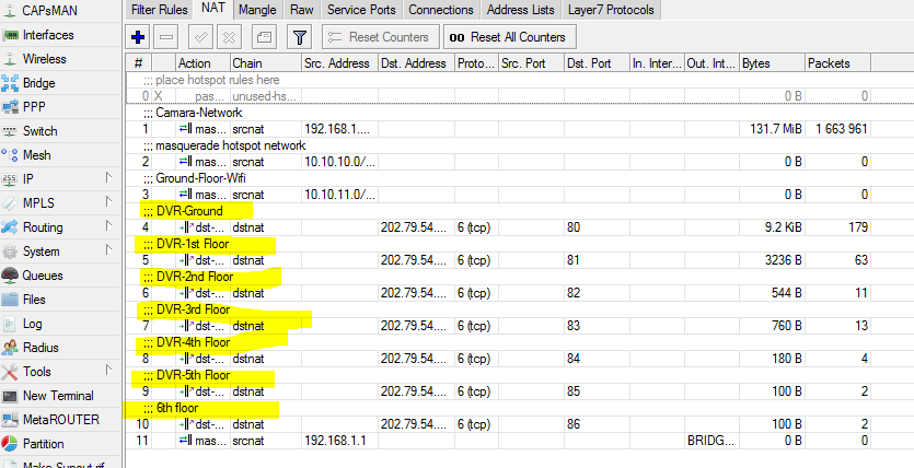
I want to configure port forwarding toward our private IPs which is connected with our four DVR system. I hv only one live IP provided by our ISP. Now i want to access all DVRs through single live IP with different port from remotely.
Live IP : 202.79.54.xxx
Private IP : 192.168.1.100 DVR 1
: 192.168.1.101 DVR 2
: 192.168.1.102 DVR 3
: 192.168.1.103 DVR 4
– First Configure DVR
1.Set IP Address
2.Set Port Forwarding – DVR 1 : port 80
DVR 2 : port 81
DVR 3 : port 83
DVR 4 : port 84
DVR 2 : port 81
DVR 3 : port 83
DVR 4 : port 84
– Open Mikrotik Router and click (New Terminal )
– Type some Script –
/ip firewall nat add chain=dstnat dst-address=202.79.54.xx dst-port=80 action=dst-nat protocol=tcp to-address=192.168.1.100 to-port=80
/ip firewall nat add chain=dstnat dst-address=202.79.54.xx dst-port=81 action=dst-nat protocol=tcp to-address=192.168.1.101 to-port=80
/ip firewall nat add chain=dstnat dst-address=202.79.54.xx dst-port=82 action=dst-nat protocol=tcp to-address=192.168.1.102 to-port=80
/ip firewall nat add chain=dstnat dst-address=202.79.54.xx dst-port=83 action=dst-nat protocol=tcp to-address=192.168.1.103 to-port=80
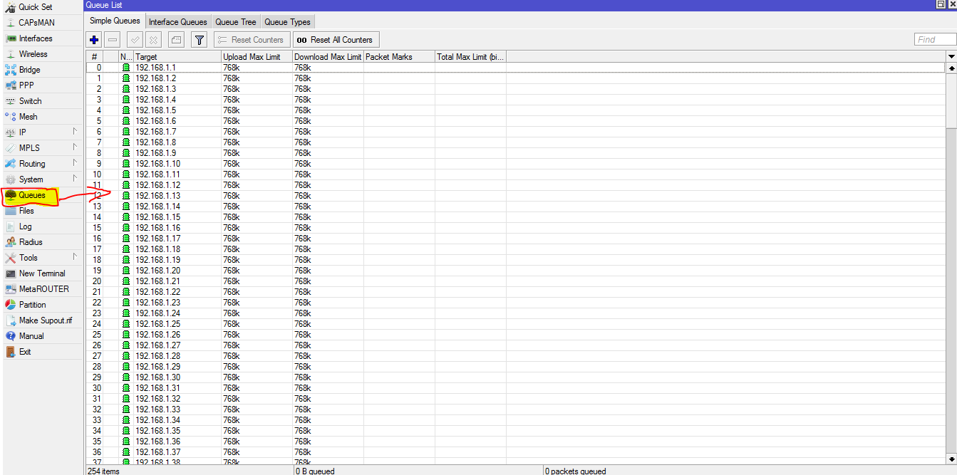
MikroTik Simple queue script – add all IP
:for x from 1 to 254 do={/queue simple add name="queue-$x" max-limit=768K/768K target="192.168.1.$x"}
Limit Youtube Bandwidth on Mikrotik

# Limit Youtube Video Stream Bandwidth on Mikrotik.
1. Login to your Mikrotik WinBox
Click on IP > Firewall, select tab : Layer7 Protocols, and click on + button and then click Ok.
You will have the new rule of Layer7 Protocols with the name streaming. You can add any other url video stream inside Regexp.
/ip firewall layer7-protocol

add comment="" name=streaming regexp="^.+(c.youtube.com).*$"
or
/ip firewall layer7-protocol

add comment="" name=streaming regexp="videoplayback|video"
2. Still in firewall window, select tab : Mangle
Here you will to create a new mangle rule.
/ip firewall mangle

add chain=prerouting action=mark-connection new-connection-mark=video_stream \

comment="Mark Streaming" passthrough=yes src-address-list=Youtuber in-interface=bridge-local
add chain=prerouting action=mark-packet new-packet-mark=video_stream_packet \

passthrough=yes connection-mark=video_stream
3. On the winbox menu click : Queues
Queue list will be shown. On tab : Simple Queue, here you will to create a new queue rule for video streaming.
/queue simple

add name=Limit_Video_Day target-addresses=192.168.88.0/24 \

direction=both disabled=no interface=bridge-local limit-at=128k/128k max-limit=256k/256k \

packet-marks=video_stream_packet parent=none priority=8 \

queue=default-small/default-small burst-limit=0/0 burst-threshold=0/0 burst-time=0s/0s \

total-queue=default-small

add name=Limit_Video_Night target-addresses=192.168.88.0/24 \

direction=both disabled=yes interface=bridge-local limit-at=0/3M max-limit=0/3M \

packet-marks=video_stream_packet parent=none priority=8 \

queue=default-small/default-small burst-limit=0/0 burst-threshold=0/0 burst-time=0s/0s \

total-queue=default-small
In this case, we want to make differences bandwidth on Day and Night
Day = 06:00am – 18:00pm – 256kbps. <Max-Limit>
Night = 18:00pm – 06:00am – 3Mbps. <Max-Limit>
4. Script
System > Script
/system script

add name=Limit_Video_Day source="/queue simple enable Limit_Video_Day; \

/queue simple disable Limit_Video_Night"

add name=Limit_Video_Night source="/queue simple enable Limit_Video_Night; \

/queue simple disable Limit_Video_Day"
5. Scheduler
System > Scheduler
/system scheduler

add disabled=no interval=1d name=Limit_Video_Day on-event=Limit_Video_Day \

start-date=oct/10/2014 start-time=06:00:00

add disabled=no interval=1d name=Limit_Video_Night on-event=Limit_Video_Night \

start-date=oct/10/2014 start-time=18:00:00
Layer 7 website blocking using Mikrotik
1. Open up Winbox and connect to your router.
1.1 On the left menu, select IP->Firewall

2. On the Firewall Windows, click on the “Layer 7 Protocols” tab

3. Click on the Add button
3.1 Under the “Name” field, type “Block”
3.2 Under the Regex field, put the text below. You can add more sites by typing in the Domain, and separating them with the pipe “|” symbol.
^.+(youtube.com|facebook.com).*$

4. Click on the “Filter Rules” tab in the “Firewall” window.
4.1 On the “General” tab, make sure that the “Forward” chain is selected.

5. On the “Advanced” tab, under “Layer 7 Protocol” select the “Block” item that we created earlier.

6. On the “Action” tab, select “reject” as the action, and then click “OK” to finish.

An alternative way to set up the blocking, is by typing (or pasting) the following in a terminal window:
/ip firewall layer7-protocol
add name=Block regexp=”^.+(youtube.com|facebook.com).*\$”
/ip firewall filter
add action=reject chain=forward layer7-protocol=Block.
add name=Block regexp=”^.+(youtube.com|facebook.com).*\$”
/ip firewall filter
add action=reject chain=forward layer7-protocol=Block.
